Routing
A router is a device that receives packets, looks at their IP address (especially the network portion), and forwards the packets along. In order to make its forwarding decision, a router uses a table. The first two entries in the table might look a little something like this:
| IP address prefix | cost | forward to |
| 12.34.00.00/16 | 5 | A |
| 88.192.0.0/12 | 4 | B |
The router builds its table by talking to other routers. We will look at two common protocols for this: the routing information protocol (RIP) and open shortest path first (OSPF). Both of these problems model routing with a graph, like below. The circles in the graph are called vertices. They represent the routers. The lines are called edges. They tell which routers are connected to which other routers. The numbers above the edges are called weights. They give the cost of using that edge.

In routing, we are interested in finding the shortest (cheapest) path from one router/vertex to another. For instance, there are many paths from A to E in the graph above. We could route packets along the long path A → B → C → G → F → E, but it's cheaper to go A → B → G → E for a cost of 3.
RIP
RIP is the older of the two protocols. It was used for routing on the early internet and it's still used today on small networks. It only works with weights of 1, like in the graph above. In RIP, each router periodically (every 30 seconds) sends out a copy of its entire routing table to all of its neighbors. Those neighbors look at the information in that table and see if they can use it to improve what they currently have. Referring to the graph above, here's what router A's table would like right after A was turned on:

The entry to B is a 1 because A is directly connected to B and can see it. However, A is not aware of any of the other vertices in the graph yet, so its costs to them are marked as ∞. In RIP, ∞ = 16. That is, anything over 15 hops away is treated as infinitely far away. The bottom row indicates which direction you would leave A in in order to get to the destination. For instance, eventually when A learns a path to C, it would also put vertex B in it the C column to indicate that the path it uses to get to C would first have to go through B. Below is what all the routers would have in the cost entries when we first turn everything on.

Let's say that B is the first to send a periodic update. So B sends its table to both its neighbors, A and C. Here is how A and C will update their tables:

From B, router A learns paths to both C and G. Since it's a cost of 1 for B to get to C, and it's a cost of 1 for A to get to B, the combined cost for A to get to C is 2 (the path is A → B → C. We also update the first hop entry to a B to indicate that A gets to C via B. The entry for G gets updated in a similar way. Router C learns a new route to A through B, as shown. Router G also gets an update from B, and it updates its table similar to what C does, but we'll leave that out.

Let's say A sends its table to B. Then B will update its table like below. In particular, since A has a path of length 5 to M, which is better than B's path to M, it will update that entry to 5+1 = 6 and mark the path as coming from A. Router A's path to R is worse than what B has, so there will be no change there. Finally, router A's path to X of length 4 is better than B's path of length 7, so B will update its entry there to 4+1 = 5.

- The algorithm RIP uses is sometimes called a distance vector algorithm. In particular, it's a variation of the well-known Bellman-Ford algorithm from computer science.
- In RIP, routers send their entire tables to each of their neighbors every 30 seconds, or sooner if they learn a new route.
- There is a 180-second timer to prevent stale routes. If a router doesn't get info about a route within that time, it removes it.
- ∞ = 16 — Rip doesn't work well on networks that are more than 15 hops long.
- Each of the edge weights in RIP must be 1. This means RIP is always finding the shortest distance in terms of hop count. It doesn't take into account the speed or cost of a link.
- RIP has slow convergence. That is, it can take a long time before all the routers know the optimal paths to the other routers. Imagine a network where the routers are all in a line, 15 routers long. The information from the router at one end will take a while to propagate down the line to the router at the other end.
- RIP doesn't do anything to deal with routing loops.
- RIP suffers from something called the count to infinity problem. See below.
Suppose we have a really simple network like the one below.

The tables for B and C would look like this:

Now suppose that the link from A to B goes down. Then B will update its cost to A to be ∞. Now suppose that C sends an update to B before B can send its update to C. Router B will look at that update, see that C can reach A in 2, and update its entry for A to 3 since that is better than ∞. The problem here is that C's route to A went through B and that link from B to A is now down. But B doesn't take that into account. Later, when B sends out its next update, C will see that B has updated entry for A to 3, and since C's path to A goes through B, C will update its entry for A to 4. After C's next update, B will do a similar thing and update its entry to 5. This will continue until both entries reach ∞.
As mentioned, the problem comes from the fact that C learned about how to get to A from B and then when B was looking for a new route to A, it took what C had even though that route passes through B itself. One way to avoid the count to infinity problem would be for routers to never advertise a route to the router they learned the route from. This is called split horizon. Another solution to the problem is that when the link from A to B goes down, B should ignore any info it gets about A for a few minutes. A third solution is immediately after the link goes down, B should send updates to its neighbors informing them of it.
OSPF
RIP is fine for small networks, but for larger networks, OSPF is preferred. OSPF also can work with edge weights that are not 1, so it can route things based on speed or cost, not just distance. In general, it is much more flexible and powerful than RIP, but it is considerably more work for network administrators to set up. OSPF is sometimes referred to as a link state algorithm.
Recall that in RIP, each router sends its entire tables to its neighbors. In OSPF, each router sends out only the costs on the edges coming into it, not its entire table. However, those updates are sent to all the routers in the network. This happens by a process called flooding, where the router sends the info to its neighbors, and they forward the info to their neighbors, who forward the info to their neighbors, etc. Further, instead of the updates being sent out every 30 seconds, they are only sent out when something changes in the structure of the network.
This whole process allows each individual router to build up a picture of what the whole graph looks like. From there, they use the famous Dijkstra's shortest path algorithm to work out the shortest paths to all the other vertices. They use this to then create their routing tables. Below is an example.
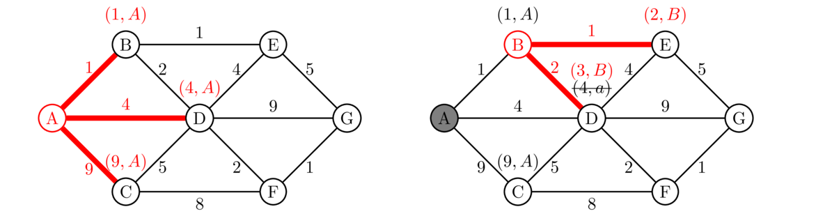
We show how Router A uses Dijkstra's algorithm to find shortest paths to the other vertices.
We start above on the left by labeling all the neighbors of A with their costs from A along with an “A” to indicate that these paths came from A. This second label will be important at the end of the process in constructing the tables. The second step of the process is shown above at the right. Since we're done at A, we shade it out to indicate that we're done with it. We won't ever come back to it. We then look at all the labels we just made and pick the one with the cheapest cost. This is vertex B that has label (1, B). We then look at B's neighbors A, E, and D. We ignore A since, as we said, we're done with it. For E, we haven't been there yet, so we label it with (2, B). The 2 indicates the cost to get to E. It costs 1 to get to B (according to its label) and 1 to get from B to E, so the cost at E is 1+1 = 2. The second part of the label is B to indicate that we got to it from B. Next, the cost to get to D from B is 1+2 = 3. This is better than the cost of 4 that's currently there, so we update its label to (3, B). So we now know that to get to D, it's better to go through B than to go directly from A to D. Below are the next two steps.

On the left, we are done with B, so we shade it out and move onto the next vertex with the cheapest costs, which is E. From E, we can get to G. It costs 2 to get to E (according to its label) and it's 5 more to get from E to G, so the current best cost to G is 2+5 = 7, and we mark it with (7, E). On the right, the next step involves searching from vertex D. Its neighbors that we're not done with are C, F, and D. Since it costs 3 to get to D and 5 to get from D to C, the total cost to C of 3 = 5 = 8 is better than what's currently there, so we relabel C. We haven't yet reached F, so we give it a label. Finally, we leave G's label alone because going through D would be a total cost of 3+9 = 12, which is worse than what we currently have for G. Here the next two steps.

Notice that once we get to searching G on the right, there are no neighbors to visit, since they are all shaded out already. The last step would be to search C, but just like with G, its neighbors are already done, so we don't get any new info.
Finally, we use all the labels to construct the routing table. The costs in the table are given directly by the labels. To get the next hop, we trace back the paths. For instance, to get the next hop for G, we start at G's label, (6, F). This tells us to go back to vertex F. We look at its label (5, D). This tells us to go back to vertex D. At vertex D, we have (3, B), which tells us to go back to B. And B has (1, A), which takes us back to the start. Reversing all this, we get the shortest path from A to G : A → B → D → F → G. The first hop of this is B, so that's what gets recorded in the table. In fact, in this case the first hop turns out to be B for all the entries, though that won't always happen. Here is the whole table:

Routing Structure of the Internet
An internet is a network of networks. The Internet that we know is composed of networks called autonomous systems. An autonomous system (AS) is a network run by various organizations, especially ISPs and telecommunications companies. As of 2020, there were about 70,000 ASes in total. Many of these ASes have large networks spreading out over much of the world, while others are much smaller. The smaller ones often have to pay the larger ones to carry their traffic. This is called transit. Two ASes that are of comparable sizes will often come to an agreement to carry each other's traffic for free. This is called peering. The biggest ASes are called Tier 1 networks. These are mostly huge companies, like AT&T and Verizon. Different ASes meet up at places called internet exchange points. These are physical locations with lots of switches and wires connecting the various networks.
Each AS has one or more blocks of IP addresses it controls. At the edge of their networks, ASes have routers running the Border Gateway Protocol (BGP). It uses a relative of RIP's distance vector algorithm, but it is much more complex as the routing needs to account for all sorts of real-world things, like money and the fact that many of the ASes are direct competitors in business. Each BGP router will announce to the others which IP addresses it has routes to. Despite its importance, there is not a lot of security built into BGP. Routers will usually trust the info they get from other routers. If a network administrator at an ISP were to purposely or accidentally advertise to other routers that they have a certain range of IP addresses, then they could get all the traffic destined for those addresses. This has happened before. Sometimes, whole portions of the internet will become unreachable for awhile because of it.